AREAS OF EXPERTISE
Soil/Rock Improvement
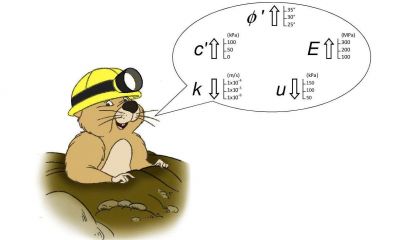
In general, the aim of soil/rock improvement is to increase the mechanical characteristics (c’, Ø’, E), decrease the permeability (k) and/or decreas the neutral pressure (u), according to the design requirements. Among the main soil improvement methods, we include permeation and hydro-fracture grouting, compaction grouting, jet grouting, deep soil mixing (DSM), cutter soil mixing (CSM), artificial ground freezing and drainage. For rock the choice is limited to penetration grouting, drainage and artificial ground freezing.
Grouting (permeation, penetration and hydro-fracturing)

Grouting is one of a number of techniques to improve the mechanical and hydraulic properties of soils and rocks. Grouting by permeation (within soil) or penetration (within rock) aims at filling and/or saturating voids with grout mixtures injected at a given pressure, without effecting any essential change to the original volume and structure of the soil or rock. When soil grain is too fine and soil permeability is too low to allow convenient treatment by permeation, hydro-fracturing (claquage) may be the right technique for soil improvement. The ground is deliberately fragmented with a grout mixture in order to increase total stresses by the wedging action of successive thin grout lenses, to fill unconnected voids and possibly to consolidate the soil under injection pressure.
Artificial Ground Freezing

Artificial Ground Freezing is a technique to temporarily improve the physical soil characteristics. The controlled extraction of heat from the ground, which cools down until the ground water temperature reaches freezing point, produces a shell or wall of frozen soil. This improved soil is now of appropriate thickness, better mechanical characteristics and lower permeability. The result is a kind of conglomerate, where the aggregates are constituted by the soil itself and the binder by the frozen water. In the first phase (the freezing phase) the aim of the operation is to freeze the ground water and to achieve the design shell/wall of frozen soil. After that, the aim is to maintain the temperature level (the maintenance phase) by accurately dosing the flux of heat extracted. Freezing is carried out by running a cooling fluid through a system of freezing pipes, previously installed into the ground to be frozen, within suitable boreholes arranged all around the volume to be excavated. Around the pipes, frozen ground columns are formed, which then meet and fuse together, making up a frozen shell/wall with the necessary shape, thickness and characteristics for the different design requirements. Two freezing processes are available: direct method (with Liquid Nitrogen as cooling fluid) and indirect method (with brine as cooling fluid).
Jet Grouting

Jet grouting is a process in which, by means of high speed jets of one or more fluids, the soil is disaggregated but not removed from place, where it is mixed with, and partially replaced by, a binding agent. This agent is delivered through radial nozzles under high pressure while revolving and drawing up the rod string from the bottom of a drilled borehole. A columnar element of consolidated ground is formed. There are three main operative methods, which differ according to the way the disaggregating and the stabilizing actions are performed, as follows:
- in the single fluid method, the disaggregating and the stabilizing actions are performed by a single cement grout fluid;
- in double fluid, both actions are performed by a cement grout fluid, assisted by an additional compressed air shroud in order to amplify the disaggregation effect;
- in the triple fluid method, disaggregation only is performed by the combined action of water and compressed air, and a separate injection of a cement grout performs the action of stabilization.
Compaction Grouting

Compaction grouting is a technique used for the controlled densification of in situ soils at depth, by means of the extrusion of a viscous grout into a compactable soil mass. A thick mortar-like mixture, grouted through a temporary casing previously installed, acts as a radial hydraulic jack, creating bulbs or lenses and thus displacing and compressing the surrounding soil.
Deep Soil Mixing

Among the techniques aimed at improving ground characteristics, deep mechanical mixing of soil or Deep Soil Mixing (DSM) has been in use now for some decades. One or more hollow rods, each carrying a special cutting tool, are driven into the ground by rotation, and subsequently withdrawn. During this operation the cement is grouted (dry or as a fluid mix). The result is a column or a column-series of improved soil made of a kind of conglomerate, where the aggregates are constituted by the soil itself and the binder by the grouted cement. The DSM elements may have waterproofing and/or structural functions.
Cutter Soil Mixing

As an alternative to DSM, deep mechanical mixing of soil may be performed by Cutter Soil Mixing (CSM), which consists of applying hydromill technology to soil mixing. A cutter machine, fitted with drums rotating on a horizontal axis, produces rectangular panels of mixed soil, which, compared to the screw methods, optimizes the final technical results and minimizes construction times and wastage. The result is a vertical diaphragm wall of improved soil made of a kind of conglomerate, where the aggregates are constituted by the soil itself and the binder by the grouted cement. The CSM diaphragm wall may have waterproofing and/or structural functions.
Drainage

Drainage may aim both at lowering the water table and improving the mechanical characteristics of soil by reducing the neutral pressure, thus increasing the effective stress and the shear strength. The drainage components may consist of pump-operated dewatering wells; drainage wells, trenches or tunnels operated by gravity; and vertical or sub-horizontal drains which discharge by means of gravity or vacuum pump.
Compensation and Uplift Grouting

Compensation Grouting and Uplift Grouting are particular applications of grouting which, in combination with an accurate displacement monitoring, allow the compensation of possible settlements of ground, buildings, utilities when occurring during tunneling or digging in general, or their controlled uplift when settlements occurred in the past. We can consider pressure grouting as the tool carrying out the compensation of settlements or controlled uplift, while monitoring can be seen as the tool for directing the pressure grouting operations. The goal achieved is a uniform compensation of settlements or the controlled uplift of ground/structures. Monitoring is carried out by an automatic system, which measures and records vertical displacement continuously and shares this data in almost real time with grouting engineers, who can steer and fine tune the grouting operations accordingly. A great deal of experience in both compensation grouting of settlements as they occur and uplift grouting of structures which already suffered settlement has been gained by now all over the world.
Directional Drilling

Directional drilling is a technology conceived and developed as an alternative to the conventional cut and cover method, for installing underground conduits. It is particularly effective when crossing underneath rivers, canals, roads, railways and urbanized areas. This technology has recently spread to other civil engineering areas and to special geo-engineering works, namely soil and rock improvement by grouting, jet grouting and artificial ground freezing. The technology is based on the principle that the actual position and path of the drilling tool may be measured and known in real time and the direction corrected by special tools and drilling bits. In such a way it is possible to steer boreholes thus avoiding excessive deviations from the design theoretical path but also to follow predetermined curved paths if necessary. By now, our experience has been consolidated in applying this technology to artificial ground freezing, soil improvement grouting, uplift and compensation grouting. One particularly significant project saw the installation of tubes à manchettes within boreholes performed by directional drilling over lengths of up to 260 m, grouted afterwards with cement and chemical mixtures using the repeated and selective method (Warsaw Metro, Line No. 2, Icotekne S.p.A.).
Diaphragm Walls and Cutoff Walls

Diaphragm walls may have a structural or hydraulic retaining function or both simultaneously. Structural diaphragm walls are made of reinforced concrete and they are installed by digging a deep and thin trench into the soil in the presence of a stabilizing fluid. The trench is then fitted with a steel reinforcement cage and concreted by the Tremie method. Usually, when the diaphragm walls have a soil retaining function they also combine the hydraulic retaining function (cutoff). When Diaphragm walls have the cutoff function only, they may be dug in the presence of different slurries: either a self-hardening slurry, which already constitutes the final and permanent filling material, or a stabilizing slurry, which is then replaced by a plastic mortar or concrete, casted by Tremie method. Diaphragm walls with only the cutoff function are generally unreinforced.
Piles (bored, CFA, displacement, secant)

Piles are reinforced concrete cylindrical elements installed underground, which conventionally have a minimum diameter of 300 mm when drilled and of 150 mm when driven. They are widely used in civil engineering as part of structural or hydraulic works, accomplishing either temporary or permanent objectives. Piles may perform the following main functions: deep foundation of structures, retaining walls, cutoff walls, stabilization of slopes and landslides. Piles may be installed using different construction methods: (i) drilling a hole in the presence of a stabilizing fluid, then fitting a steel reinforcement cage and concreting with the Tremie method; (ii) drilling by Continuous Flight Auger (CFA) or displacement tool, then concreting while withdrawing the drilling rod and inserting a steel reinforcement cage into the fresh concrete. Piles may also be located on alignments and be secant, thus producing continuous wall with structural and/or cutoff function.
Micropiles

Micropiles are small diameter piles which: (i) include a structural element to transfer loads in depth and/or limit displacements; (ii) may be drilled by means of a small rig. Conventionally a micropile has a maximum diameter of 300 mm if drilled and 150 mm if driven. The reinforcement may consist of a steel pipe or profile or of a cage of steel bars. The filling material may be cement grout or mortar or concrete. The main functions of micropiles are the following: underpinning existing structures, foundation of new structures, retaining walls, stabilization of slopes and landslides, anchoring of structures.
Berlin Walls

Berlin walls are flexible retaining structures, made from vertical micropile alignments. According to the height of the ground to be retained they may follow a cantilever or anchored/multi-anchored wall design. Berlin walls may be built according to two different methods: (i) relatively tight spacing (from 0.3 m to 1.0 m) and reinforcement by steel pipe or H profile; (ii) relatively wide spacing and reinforcement by steel H profile with precast plates or wood planks inserted in between for the whole excavation height.
Ground Anchors

Ground anchors are structural elements capable of transferring traction forces down to bearing layers of soil or rock. Reinforcement may be by steel strands, bars or profiles. The main functions of ground anchors are the following:
- to anchor retaining structures to deep soil layers; for example, gravity walls, diaphragm walls berlin walls;
- to transfer traction forces acting on the foundation of structures to deep soil layers;
- to oppose uplifting forces acting below the foundation of structures built under the water table;
- to ensure the stability of structures located on unstable slopes;
- to improve the stability of slopes and landslide areas;
- to prestress rock masses or massive concrete structures.
Tunnelling

Nowadays TBM is the most utilized and safest construction method for tunnelling, particularly when the tunnel length justifies its installation and use. Nevertheless, conventional methods are still used and they often require a preliminary improvement of the soil surrounding the tunnel to be bored, in order to increase the mechanical characteristics (loose soils and weathered rocks) and lower the permeability (non cohesive soils and fissured rocks). The main soil improvement techniques used to allow a safe conventional tunnelling are: grouting, jet grouting, forepoling, soil nailing and drainage ahead of the face.
Dams

Of all the geotechnical engineering works, dams require the largest range of specialized techniques, including for example, extensive soil investigation, improvement of the mechanical characteristics of the foundation soil, underground cutoff, ground anchors to stabilize the abutments and the foundation of blondins, geotechnical instrumentation, built-in and compaction of embankments, etc…. Nowadays, the job of repairing existing dams and carrying out safety maintenance work, becomes more and more important. When the functioning of a dam has been compromised by phenomena which have appeared after construction (such as, settlements, displacements, seepage or erosion), it will be necessary, together with the repair work, to carry out operations aimed at the removal of the causes. Hydraulic phenomena are usually countered by interventions to reduce the permeability of soil and rock located under the dam foundation and also, sometimes, of the massive body of the dam. Structural defects may be effectively repaired through a combination of grouting to seal fissures together with the use of active anchors to apply a prestressing to the massive concrete body, extending to the rock beneath the foundation. Possible settlement and displacement phenomena may be tackled by improving the mechanical characteristics of the soil and rock under the foundation.
Landslide Stabilization by Soil Reinforcement and Deep Drainage

One of the most complex problems that a geotechnical engineer has to tackle is how to design and perform the stabilization of landslides. The main technical approaches for slope and landslide stabilization are as follows: (i) structural; (ii) drainage; (iii) displacement of surface masses; (iv) improvement of the mechanical characteristics of soils. These may be applied separately or in combination. The main specific techniques adopted are: drainage wells, trenches and tunnels; micro drains, bored piles, diaphragm walls, micropiles, berlin walls and ground anchors.
Mechanized Vertical Shafts VSM (Vertical Shaft-sinking Machine)

VSM (Vertical Shaft-sinking Machine) is a recent innovation in mechanized technology for boring and simultaneously lining by the sinking of vertical circular shafts, with inner diameter from 4.5 to 10.0 m, down to a maximum depth of 80 m or more. It is applicable both above and below the water-table. The first application dates back to 2004, in Kuwait. Since then, more than 50 VSM shafts have been installed, in 8 different countries throughout Europe, Asia and America, down to a maximum depth of 83 m, which was reached in St. Petersburg. At the moment 10 VSM equipment groups are available in the world. The VSM system, as well as enabling a faster and safer excavation compared with conventional techniques, allows the whole sinking to be completed without operators having to descend into the shaft and without lowering the surrounding water-table. This means a considerable increase in safety for operators and a significant reduction in the effects on the surrounding environment, particularly relevant when operating in urban areas.
Raise Boring


Raise Boring is a technology to install vertical or sub-vertical shafts within rock or any other stable material. It was conceived and developed during the 60s in the mining industry. At that time it represented an innovation in the field of drilled shafts. Later on, Raise Boring spread to civil engineering applications in order to bore shafts and recently also drifts, the latter being a further innovation. This technology allows the boring of circular holes with a diameter of between 0.6 m and 6.0 m and a length of up to 1000 m or more. Raise Boring is always performed either to connect the surface of the ground with an underground space (a cave or tunnel) or to connect two underground spaces. Using a RBM (Raise Boring Machine) and starting from one of the two spaces that are to be connected, a pilot hole is drilled along the designed shaft or tunnel axis, right through to the second space. Here, the RBM is hooked up to a reamer, which is set rotating, and brought back by the RBM via traction. Thus the boring phase proceeds in the opposite direction to the previous drilling stage, widening the pilot hole up to the final specified dimensions. In common with other mechanized excavation, the main advantages of applying Raise Boring technology are: increased safety for operational staff, short excavation times, regularity of finished surfaces, no over-excavation, and low environmental impact.